

Products


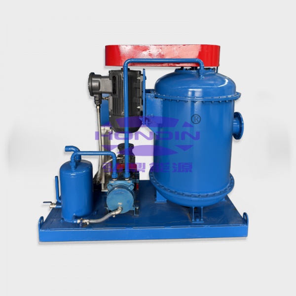
Mud Gas Separator
During drilling operations, drilling fluid gas separators are ideal equipment when encountering blowouts, well kicks, or when operators are drilling with underbalanced mud columns. HONDIN's drilling fluid gas separators are primarily used to separate large amounts of free gas from drilling fluids, including toxic gases such as hydrogen sulfide. Field testing has proven that HONDIN's drilling fluid gas separators are a highly reliable and crucial safety device.
I. Parameters
| Model | ZYQ600 | ZYQ800 | ZYQ1000 | ZYQ1200 |
| Main body diameter | 600mm | 800mm | 1000mm | 1200mm |
| Capacity | 120~300m³/h | 180~260m³/h | 240~320m³/h | 260~380m³/h |
| Inlet pipe | 5' | 5' | 5' | 5' |
| Output pipe | 6' | 6' | 8' | 10' |
| Gas discharge Vent Line | 6' | 6' | 8' | 8' |
| Weight | 1200kg | 1600kg | 2000kg | 2500kg |
| Dimensions | 1800×1800×5500mm | 1900×1900×5700mm | 2000×2000×5860mm | 2200×2200×6634mm |
II. Product Introduction
The gas-invaded drilling fluid enters the equipment from the inlet of the drilling fluid gas separator, falls on a series of specially designed internal baffles along the inner wall, collides, increases the exposed surface area, flows downward, creates a turbulent state, and separates the gas from the drilling fluid. The free gas is discharged through the gas outlet on the top of the tank. The exhaust pipe length is determined and equipped on site and led to a safe place, and the degassed drilling fluid is discharged into the circulation tank.
III. Working Principle:
Gas-infiltrated drilling fluid enters the equipment tangentially through the inlet of the drilling fluid gas-liquid separator. It flows down the inner wall onto a series of specially designed internal baffles, colliding with them, increasing the exposed surface area, and flowing downwards, creating turbulence and separating the gas from the drilling fluid. The free gas is discharged through the gas outlet on the top of the tank. The length of the exhaust pipe is determined and provided on-site, and it is led to a safe location. The degassed drilling fluid is discharged into the circulation tank.
IV. Installation and Maintenance:
1. Installation
Generally, the drilling fluid gas-liquid separator is installed on the ground next to the No. 1 mud tank. The ground must be level, firm, and have pre-drilled anchor bolt pits.
During installation, a crane is used to lift the main body vertically using the lifting lugs on the top. It is then slowly lowered, and steel wire ropes are used to tighten the main body to the ground at three evenly distributed points on the top, ensuring the main body is perpendicular to the ground. Anchor bolts are then poured and tightened.
After installation, lead the No. 2 vent pipeline to a location 60-80m from the wellhead (the pipeline is to be supplied by the customer; if required by the manufacturer, specify when ordering). Connect the No. 3 slurry inlet to the rotary blowout preventer or throttling manifold. Close the No. 4 drain valve and open the No. 7 slurry outlet valve. Connect the pipeline to the No. 1 mud tank. During transport, remove the manifold, loosen the taut wire rope, use a crane to support the top of the main body, loosen the anchor bolts, and place it horizontally. The ladder can be used as a transport support.
2. Maintenance:
When not in use, drain the drilling fluid from the equipment and flush it with water. It is strictly forbidden to store mud inside the drilling fluid-gas separator, as the mud will harden and become unusable.
Please consult your account manager for more details!


 Copy product links
 Long by picture save/share
INQUIRY


Add Successfully
INQUIRY
Add Successfully
Hot product


Add: No.462 Jinggao South Road, Gaoling District, Xi'an, Shaanxi Province, China
Mob/WhatsApp: +86 186 2931 2932/ +86 187 2900 8271
E-mail: sales@hondinchina.com

Follow us:

点击右上角
分享给朋友吧
点击右上角
分享给朋友吧
Copyright © Xi'an Hondin Energy Technology Co., Ltd. All rights reserved
Copyright © Xi'an Hondin Energy Technology Co., Ltd. All rights reserved