

Products


Skid-mounted fracturing flowback fluid treatment system complete equipment
Unveil the composition of pollutants in fracturing flowback fluid, categorized into original formation pollutants like natural radioactive substances, inorganic materials, metal elements, gases, and hydrocarbons, whose quantities vary by oil and gas field location and geology. Also, explore the chemical components of fracturing fluid, including proppant
1. Equipment introduction
1.1 List of main equipment
| Serial number | Device Name | quantity | Dimensions (length x width x height) mm |
| 1 | Dosing skid | 1 | 6000×2500×2900 |
| 2 | High efficiency reaction skid | 1 | 12000×2500×2900 |
| 3 | Fine filtration skid | 1 | 12000×2500×2900 |
| 4 | Ion Removal Processing Skid | 1 | 12000×2500×2900 |
| 5 | Sludge treatment skid | 1 | 10000×2500×2900 |
| 6 | Vertical sludge storage tank | 1 | 9000×2500×2600 |
| 7 | appendix | 1 | Connect pipes, cables, ladders, etc. between equipment |
1.2 Introduction to main equipment
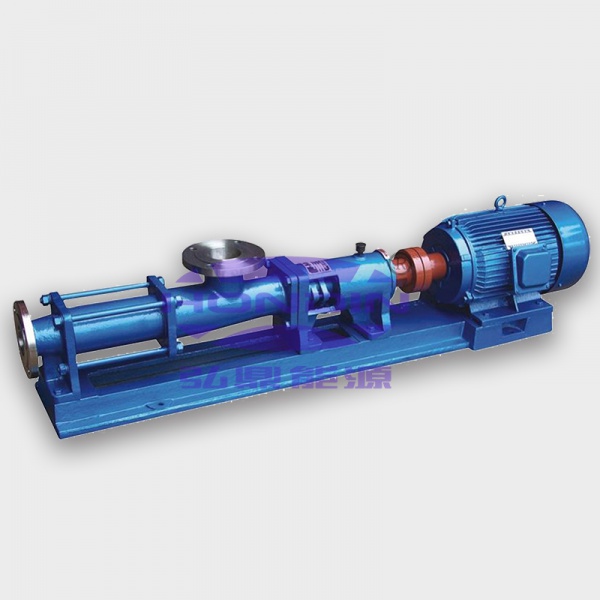
1.2.1 Dosing skid
The dosing skid consists of a drug dispensing box, a drug storage box, a high-efficiency stirring device, a dosing pump, an electronic control system, a skid body, a base, and pipelines. It is used to configure and store chemical agents, and set the dosage according to process requirements for quantitative dosing. The main structural materials such as the skid body and the base are made of carbon steel, and the pipeline materials are stainless steel and UPVC.
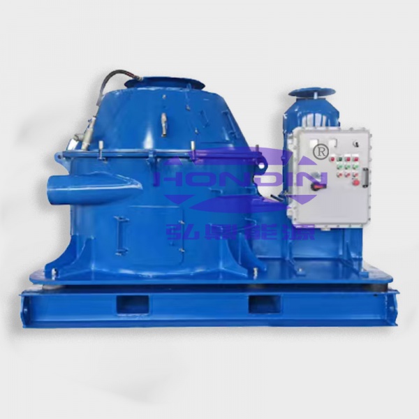
1.2.2 High-efficiency reaction skid
The high-efficiency reaction skid consists of a continuous high-efficiency mixing reactor, a primary high-efficiency flotation system, a secondary high-efficiency flotation system pump, a sludge tank, an intermediate water tank, a pump, an electronic control system, a skid body, a base, and pipelines. After the raw water is fully mixed and reacted with the chemical agent in the reactor, it enters the primary high-efficiency flotation system for flotation separation. The water after the primary flotation separation enters the secondary high-efficiency flotation system for treatment and then enters the intermediate water tank. The main structural materials such as the skid body and the base are made of carbon steel, and the pipeline material is stainless steel.
1.2.3 Fine filtration skid
The fine filtration skid consists of a primary filtration system, a fine filtration system, a backwash system, an electric control system, a skid body, a base, pipes, valves, etc. The water in the intermediate water tank is pumped to the filtration system by a pressure pump for filtration and then discharged. The filtration system adopts fully automatic filtration and fully automatic backwashing. The main structure of the skid body, base, etc. is made of carbon steel, and the pipe is made of stainless steel. The main body of the filter tank is made of carbon steel, and the interior is anti-corrosive with glass flake paint. The pipe fittings welded to the tank are made of stainless steel.
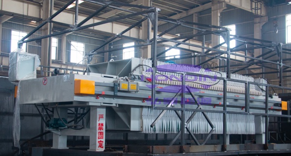
1.2.4 Sludge treatment skid
The sludge treatment skid consists of a container, a filter press system, a sludge conveying system, a water tank, a pump, a pipe, a valve, etc. The main structure of the container, water tank, etc. is made of carbon steel, and the pipe is made of stainless steel.
1.2.5 Vertical sludge storage tank
Volume 25m³, composed of tank body, base, level gauge, guardrail, ladder, etc. The main structure of the tank body, base, guardrail, ladder, etc. is made of carbon steel, and the pipe material is stainless steel. The inside of the tank body is made of reinforced epoxy resin and glass fiber cloth for corrosion protection, and the pipe fittings welded to the tank body are made of stainless steel
The sludge treatment system and ion removal system are configured to reduce the scum and bottom mud generated during the treatment of fracturing flowback fluid. The boron ions and chloride ions in the treated water are selectively removed to meet the requirements of the treated water for fracturing fluid refilling.
| Serial number | Device Name | Reinjection equipment configuration after processing | Configuration of equipment for fracturing fluid re-mixing after treatment | Remark |
| 1 | Dosing skid | ※ | ※ | |
| 2 | High efficiency reaction skid | ※ | ※ | |
| 3 | Fine filtration skid | ※ | ※ | |
| 4 | Ion Removal Processing Skid | ※ | ||
| 5 | Sludge treatment skid | Optional | ||
| 6 | Vertical sludge storage tank | Optional | ||
| 7 | appendix | ※ | ※ |
The composition of pollutants in fracturing flowback fluid can generally be divided into two types: original pollutants in the formation and chemical components in the fracturing fluid. Original pollutants in the formation include natural radioactive substances (uranium, thorium, radium, radon, strontium and potassium), inorganic substances and metal elements (aluminum, arsenic, barium, bromine, cadmium, chloride, chromium, iron, manganese, mercury, nickel, sodium, vanadium and zinc), gases (CH4 and CO2), hydrocarbons (polycyclic aromatic hydrocarbons (PAHs), phenols, long-chain fatty acids, alkylbenzenes and aliphatic hydrocarbons), etc. These substances vary greatly due to the different locations and geological conditions of oil and gas fields. The chemical components in the fracturing fluid mainly refer to the various chemical agents required to improve the fracturing efficiency during the hydraulic fracturing process, mainly including proppants, drag reducers, gel breakers, bactericides, etc. These substances are difficult to degrade in nature and are the main targets of treatment.
Untreated fracturing flowback fluid contains a large amount of difficult-to-degrade organic matter and is generally acidic or alkaline. It may corrode or clog pipelines during reuse, and may cause water pollution when discharged. The radioactive elements and metals in it are likely to pollute the soil and reduce soil fertility.
2. Design parameters and basic requirements
2.1 Use environment
1) Ambient temperature: -30 to 45℃;
2) Relative humidity: maximum 95%;
3) Installation environment: well site or fixed treatment site;
4) Climate: humid and corrosive.
2.2 Scope of equipment use
This equipment is suitable for scraper system fracturing flowback fluid, slippery water system fracturing flowback fluid, clean fracturing fluid system fracturing flowback fluid, oilfield sewage, oilfield produced water, etc. generated during drilling and production increase of oil wells, gas wells, and coalbed methane wells.
2.3 Treatment requirements
Designed processing capacity 30m³/h, 24h continuous operation.
After being treated by this equipment, the return fluid reaches the A2 reinjection standard (suspended solid content <3 mg/L, median diameter of suspended particles <2µm, oil content <5mg/L); or reaches the water quality index for fracturing fluid preparation and reuse (the prepared fracturing fluid meets the requirements of 'General Technical Conditions for Fracturing Fluids' SY/T 6376 2008).
3. Process Introduction


 Copy product links
 Long by picture save/share
INQUIRY


Add Successfully
INQUIRY
Add Successfully
Hot product


Add: No.462 Jinggao South Road, Gaoling District, Xi'an, Shaanxi Province, China
Mob/WhatsApp: +86 186 2931 2932/ +86 187 2900 8271
E-mail: sales@hondinchina.com

Follow us:

点击右上角
分享给朋友吧
点击右上角
分享给朋友吧
Copyright © Xi'an Hondin Energy Technology Co., Ltd. All rights reserved
Copyright © Xi'an Hondin Energy Technology Co., Ltd. All rights reserved