

Cases
Current Status and Improvement Measures of Drilling Fluid Solids Control Systems
Time:
2025-11-10
In the drilling process, excellent drilling fluid performance is a prerequisite for improving drilling speed, reducing drilling costs, preventing downhole accidents, and protecting oil and gas producing formations. The drilling fluid solids control system is the guarantee for maintaining drilling fluid performance.
With the development of the petroleum exploration industry, drilling depths are constantly increasing, and the formations encountered are becoming increasingly complex. Special wells such as deep wells, ultra-deep wells, horizontal wells, and underbalanced wells are becoming more common, placing higher demands on drilling fluid solids control systems.
In recent years, solids control systems have seen significant improvements in technology, from drilling fluid circulation tanks to solids control equipment, and the process flow has become more rational. However, many misconceptions still exist regarding the matching of solids control systems.

1. Drilling Fluid Circulation Tank.
The effective volume of the drilling fluid circulation tank must be sufficient to accommodate the maximum circulation volume of drilling fluid during drilling, and have adequate reserve capacity. It must also be capable of readily engaging in circulation and controlling the well in emergencies. In recent years, with the continuous expansion of overseas markets and the increasing demands of drilling technology on drilling fluid solids control systems, there has been a phenomenon of blindly expanding the volume of drilling fluid circulation tanks.
Excessive volume of the solids control system increases the cost of drilling rig relocation and drilling fluid costs. Therefore, a reasonable volume is the goal pursued by users.
The size of a single tank and the number of circulation tanks in a solids control system are generally determined based on factors such as the height of the derrick base, local transportation conditions, and the effective volume required by the drilling rig. Sufficient space must be provided on the surface of the circulation tank to accommodate solids control equipment, agitators, and drilling fluid transfer pumps. Additionally, space must be considered for connecting pipelines, mud tanks, accessories, pump suction and discharge pipelines, water pipelines, and other equipment. The volume of each compartment is primarily determined by the installation space available for solids control equipment such as vibrating screens, desanders, desilters, and centrifuges, as well as their auxiliary equipment.
2. Solids Control System Process Flow and Equipment Matching.
The entire solids control system's process flow should meet the requirements for five stages of solids control of drilling fluid (screening—degassing—desanding—desilting—centrifugation) and mud weighting. Optimized matching of solids control equipment is crucial. The processing capacities of stages 1-5 of the solids control equipment should be mutually matched, with appropriate spacing between separated particle sizes and a certain degree of overlap, allowing smaller particles not completely processed by the previous stage to still be processed by the next stage.
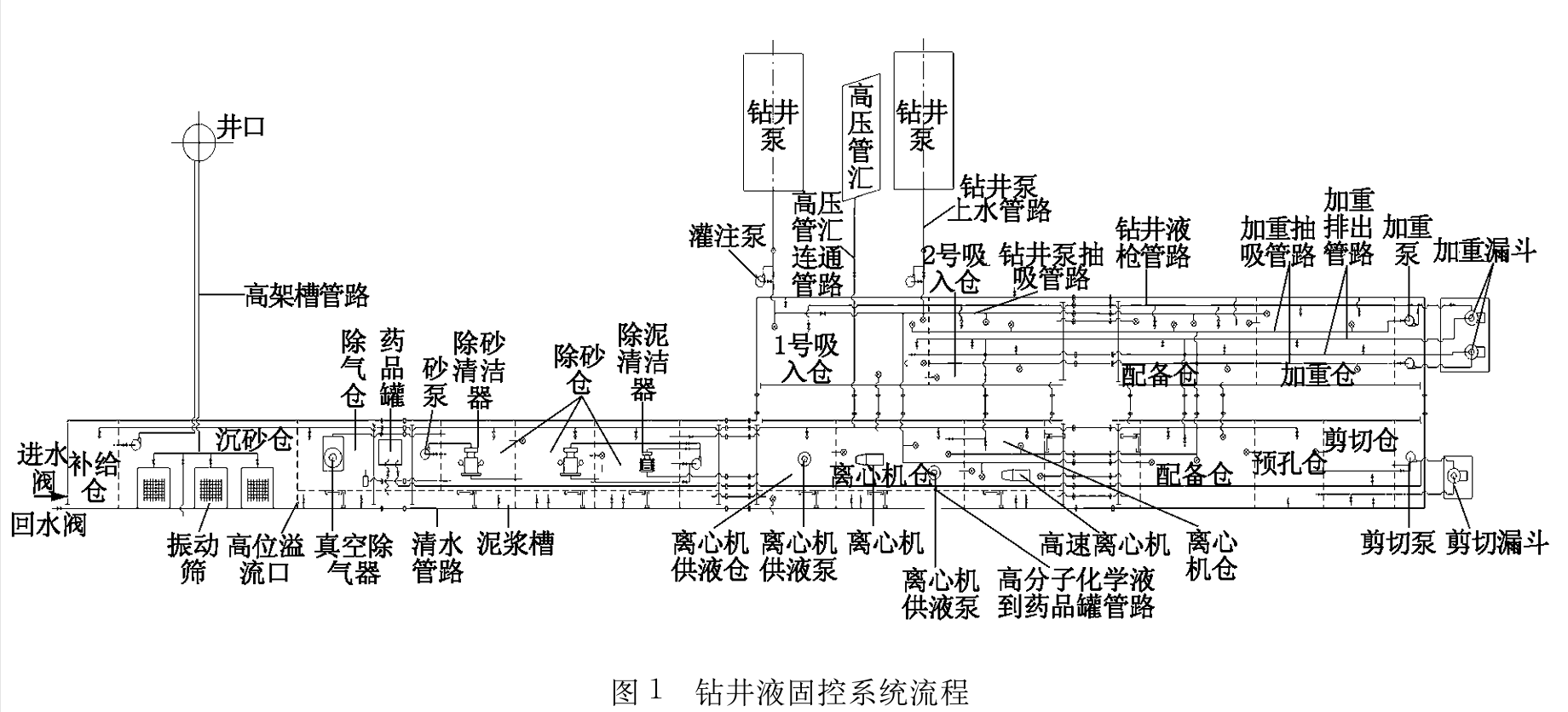
2.1 Drilling Fluid Purification and Circulation Process.
Wellhead mud returned via pipelines can be individually or simultaneously transported to various vibrating screens. After processing by the vibrating screens, it enters the sand settling chamber. Mud overflowing from the sand settling chamber enters the desanding chamber via the mud tank (if mud gas intrusion occurs, a vacuum deaerator can be activated to draw mud from the deaerator chamber for degassing before it enters the desanding chamber).
Mud processed by the desander enters the desilting chamber. Mud processed by the desilter enters the centrifuge chamber via the mud tank. Mud processed by the centrifuge enters the drilling fluid suction chamber via the mud tank. It is then repeatedly pumped into the well for reuse by the drilling pump. A more reasonable flow chart for the drilling fluid solids control system is shown in the figure below.
2.2 Process Flow and Selection of Vibrating Screens.
Drill cuttings generated at the bottom of the well during drilling are carried to the surface by the drilling fluid. Vibrating screens are the first, fastest, and largest-volume solids control equipment for removing drill cuttings, and are an essential first-stage treatment device for drilling.
The technical level of a vibrating screen is mainly reflected in its processing capacity (processing volume and separated particles), operational reliability, lifespan, and ease of operation and maintenance. With the size, content, and viscosity of the drilling fluid solid particles remaining constant, the greater the dynamic shear stress on the solid particles, the greater the initial resistance to particle movement, and the lower the particle transport speed.
Theoretical research on vibrating screens abroad has fully recognized this point. Before the drilling fluid flows from the distributor into the vibrating screen, a drilling fluid impact trough is installed to avoid direct scouring of the screen by the drilling fluid, minimizing the dynamic shear stress on the drilling fluid returning from the wellhead.
Not only is the force and movement of solid particles more rational, but it also reduces drilling fluid leakage and increases drilling fluid throughput, extending the service life of the screen. However, due to differences in materials, processing technology, processing precision, and compatible general equipment among manufacturers, the actual technical performance of products varies significantly.
Therefore, when selecting a vibrating screen, it is crucial to understand the materials, processing technology, processing precision, and compatible general equipment in detail, rather than simply relying on the stated technical parameters. Besides selecting a suitable screen based on the solid particle size distribution, another important factor to consider when choosing a vibrating screen is its permissible throughput. The vibrating screen's throughput capacity should be able to accommodate the maximum discharge rate during drilling.
Factors affecting the vibrating screen's throughput include its own motion parameters, drilling fluid type, density, viscosity, solid particle size distribution and content, and screen size. To meet the requirements of large discharge rates, sometimes 2-3 vibrating screens need to be used in parallel.
2.3 Hydrocyclone Working Process and Equipment.
Most solids control equipment manufacturers in my country can produce hydrocyclones, namely desanders and desilters. The main quality indicator for hydrocyclones is wear resistance, and their performance is primarily determined by the separation particle size, D50. A lower D50 indicates better separation efficiency.
When configuring desanders and desilters, it's important to ensure that the particle separation ranges have both sufficient spacing and overlap. According to the classification standards and separation particle sizes of hydrocyclones, hydrocyclones with a cylindrical volute inner diameter of Φ150–300 mm and a separation particle size of 44–74 μm are classified as desanders.
Hydrocyclones with a cylindrical volute inner diameter of Φ100–125 mm and a separation particle size of 15–44 μm are classified as desilters. However, many desanders and desilters actually used in the field separate particles with similar sizes (desanders for 20–50 μm and desilters for 15–45 μm). Drilling fluid treated by a desander is then treated by a desilter, rendering the desilter ineffective at removing solid particles. The main reason for this is that many hydrocyclones are poorly manufactured and fail to meet drilling process requirements. Therefore, many users opt for a two-desander setup instead of a single desander and desilter.
Some users simply install a second desander at the original desilter location without altering the process flow. This approach is not recommended, as both desanders have identical performance parameters. A parallel process flow should be used, serving as backups for each other or increasing the drilling fluid throughput during rapid drilling.
For special wells with high drilling fluid performance requirements, a reasonable setup remains one desander and one desilter in series. However, when selecting desanders and desilters, products with different particle size ranges should be chosen. For example, a desander with a separation particle size of 47–76 μm and a deslimor with a separation particle size of 15–47 μm can achieve a better treatment effect.

2.4 Centrifuge Process Flow.
Drilling industry experts generally agree on the crucial role of centrifuges in solids control systems. Most drilling teams in China are equipped with medium-speed centrifuges with main unit power of 18.5, 22, 37, or 45 kW and rotation speeds of 1300–2200 r/min. Currently, centrifuges are mainly divided into two types: medium-speed centrifuges and high-speed centrifuges.
Medium-speed centrifuges refer to centrifuges with a rotation speed of 1300–2200 r/min, generating a centrifugal force approximately 800 times that of gravity, and a processing capacity of 40–60 m³/h. These centrifuges are used to remove solid particles of 5–7 μm. High-speed centrifuges refer to centrifuges with a rotation speed of 2500–3300 r/min, generating a centrifugal force approximately 1200–2100 times that of gravity, and capable of separating particles with a size of 2–5 μm.
High-speed centrifuges are divided into two types: one is a fully variable frequency control high-speed centrifuge. This centrifuge's processing capacity can be automatically adjusted according to the drilling fluid properties, and it can effectively control the drilling fluid properties through real-time load monitoring and full frequency conversion automatic closed-loop control technology. It is an ideal solid phase purification device for drilling deep wells and horizontal wells with special process requirements.
Another type is the fixed-speed high-speed centrifuge. These centrifuges typically have 2-3 speeds higher than ordinary centrifuges. Operators assess the drilling fluid's properties and manually adjust the centrifuge speed to achieve better drilling fluid treatment results. Centrifuges have played an increasingly important role in drilling fluid treatment. Many drilling teams are equipped with two centrifuges. It's important to note that when using two centrifuges with identical technical specifications (generally medium-speed centrifuges, sometimes with different processing capacities), a parallel process should be used for backup or to increase the drilling fluid processing capacity during rapid drilling.
Currently, foreign companies such as Derrick and Swaco have produced fully variable frequency controlled high-speed centrifuges. These high-speed centrifuges are expensive and require highly skilled operators, necessitating operation and maintenance by specialized electrical engineers. Currently, only a few domestic drilling teams operating overseas are equipped with this type of high-speed centrifuge.
In China, for special wells with high drilling fluid performance requirements, it is recommended to use a process involving a medium-speed centrifuge and a domestically produced high-speed centrifuge connected in series. The drilling fluid, after being processed by a medium-speed centrifuge, enters the supply tank of a high-speed centrifuge. After further processing by the high-speed centrifuge, it enters the circulation system for reuse.
At this point, the solid phase of the drilling fluid is effectively purified, which is beneficial for extending the service life of downstream equipment (drilling pumps, drilling tools, downhole instruments, etc.), saving mud material consumption, and increasing mechanical drilling speed.

3. Conclusions.
1) Select vibrating screens with good performance and reasonable design, and choose the required number and screen size of vibrating screens according to the properties of the drilling fluid.
2) Select desanders and desilters with good performance and reasonable matching parameters, and adopt a series process flow to achieve better desander and desilter removal effects.
3) Use a series process flow of medium-speed and high-speed centrifuges to improve the service life of downstream equipment (drilling pumps, drilling tools, downhole instruments, etc.), save mud material consumption, and increase mechanical drilling rate.
Statistical analysis results show that approximately 90% of the daily maintenance cost of drilling fluid during drilling is related to solids control. The cost of barite, a weighting agent in drilling fluid, accounts for approximately 75% of the total material cost of drilling fluid.
Therefore, correctly selecting and using solids control systems and equipment can significantly remove drill cuttings, reduce the consumption of drilling fluid and its associated materials and treatment agents, and thus achieve better economic benefits.
你的喜欢,就是我坚持写下去的能量器
YouArticle
已有0人推荐


Hot Cases
-

How an Oily Sludge Treatment System Improves Oilfield Waste Management
-
HONDIN Energy Slurry Mixers: High-efficiency slurry mixing solutions suitable for various working conditions
-
The successful delivery of hazardous waste containers helps customers achieve standardized temporary storage management of hazardous waste.
-
Reco Water quality deterioration, easy clogging, tight deadlines? This skid-mounted oilfield and fracturing flowback fluid treatment system is designed for complex operating conditions!
-
Why are engineering projects becoming increasingly reliant on mud solids control systems?
-
Environmentally friendly treatment of drilling waste – achieving full compliance with solid and liquid standards and resource reuse.
-
Exploration of Improvements to Drilling Mud Non-Drop Equipment
-
Core Advantages and Application Analysis of Coalbed Methane Well Solids Control Systems
-
Core equipment of mud-free system
-
Current Status and Improvement Measures of Drilling Fluid Solids Control Systems
-
Understanding the Mud-Free System in One Article
-
Understanding Drilling Waste Management Systems in One Article


Add: No.462 Jinggao South Road, Gaoling District, Xi'an, Shaanxi Province, China
Mob/WhatsApp: +86 186 2931 2932/ +86 187 2900 8271
E-mail: sales@hondinchina.com

Follow us:

点击右上角
分享给朋友吧
点击右上角
分享给朋友吧
Copyright © Xi'an Hondin Energy Technology Co., Ltd. All rights reserved
Copyright © Xi'an Hondin Energy Technology Co., Ltd. All rights reserved